Step by step in 3D printing
FreeCAD 0.20.2
- Handbook –
Author: Vojislav Aleksić
Technical school, Pirot
- Lesson 1 – About handbook 2
- Lesson 2 – 2D drawing 5
- Lesson 3 – 2D drawing: defining constraints, drawing geometric shapes 18
- Lesson 4 – 3D model: Prismatic parts 27
- Lesson 5 – 3D model: Axisymmetric parts 37
- Lesson 6 – 3D model:Creation of typical shapes by pouring sections (Loft) 49
- Lesson 7 – 3D model: Creation of typical shapes by drawing along a curve (Additive pipe) 54
Lesson01 – About handbook
The handbook follows a step by step methodology and teaches you to use FreeCAD design software for building parametric 3D solid components as well as creating 2D drawings. This handbook not only focuses on the usage of the tools and commands of FreeCAD but also the concept of design. Every chapter in this handbook contains tutorials that provide users with step by step instructions for creating designs and drawings with ease. Every chapter ends with hands-on test that allow users to experience the user friendly and powerful capabilities of FreeCAD to enhance the skills at the end of every chapter and additional notes and tips. The instructions to perform any action are provided by maximum number of illustrations so that the user can perform the actions discussed in the book easily and effectively. There are a lot of illustrations that make the learning process effective. Moreover most of the tools in this handbook are discussed in the form of step by step tutorials. Starting with the basics, you’ll explore the FreeCAD interface and terminology, setting a strong foundation for your 3D modeling adventure.
What is FreeCAD?
FreeCAD is an open-source parametric 3D modeling application, made primarily to design real-life objects. Parametric modeling describes a certain type of modeling, where the shape of the 3D objects you design are controlled by parameters. For example, the shape of a brick might be controlled by three parameters: height, width and length. In FreeCAD, as in other parametric modelers, these parameters are part of the object, and stay modifiable at any time, after the object has been created. Some objects can have other objects as parameters, for example you could have an object that takes our brick as input, and creates a column from it. You could think of a parametric object as a small program that creates geometry from parameters. FreeCAD is not designed for a particular kind of work, or to make a certain kind of objects. Instead, it allows a wide range of uses, and permits users to produce models of all sizes and purposes, from small electronic components to 3D-printable pieces and all the way up to buildings. Each of these tasks have different dedicated sets of tools and workflows available.
FreeCAD is also multiplatform (it runs exactly the same way on Windows, Mac OS and Linux platforms), and it is open-source. Being open-source, FreeCAD benefits from the contributions and efforts of a large community of programmers, enthusiasts and users worldwide. FreeCAD is essentially an application built by the people who use it, instead of being made by a company trying to sell you a product. And of course, it also means that FreeCAD is free, not only to use, but also to distribute, copy, modify, or even sell.
Installing
FreeCAD uses the LGPL license, which means you are free to download, install, redistribute and use FreeCAD the way you want, regardless of the type of work you’ll do with it (commercial or non-commercial). You are not bound to any clause or restriction, and the files you produce with it are fully yours. The only thing that the license prohibits, really, is to claim that you programmed FreeCAD yourself!
Setting basic preferences
Once FreeCAD is installed, you might want to open it and set a couple of preferences. Preferences settings in FreeCAD are located under menu Edit – Preferences-General.
Language: FreeCAD will automatically pick the language of your operating system, but you might want to change that.
General – Language – Change language
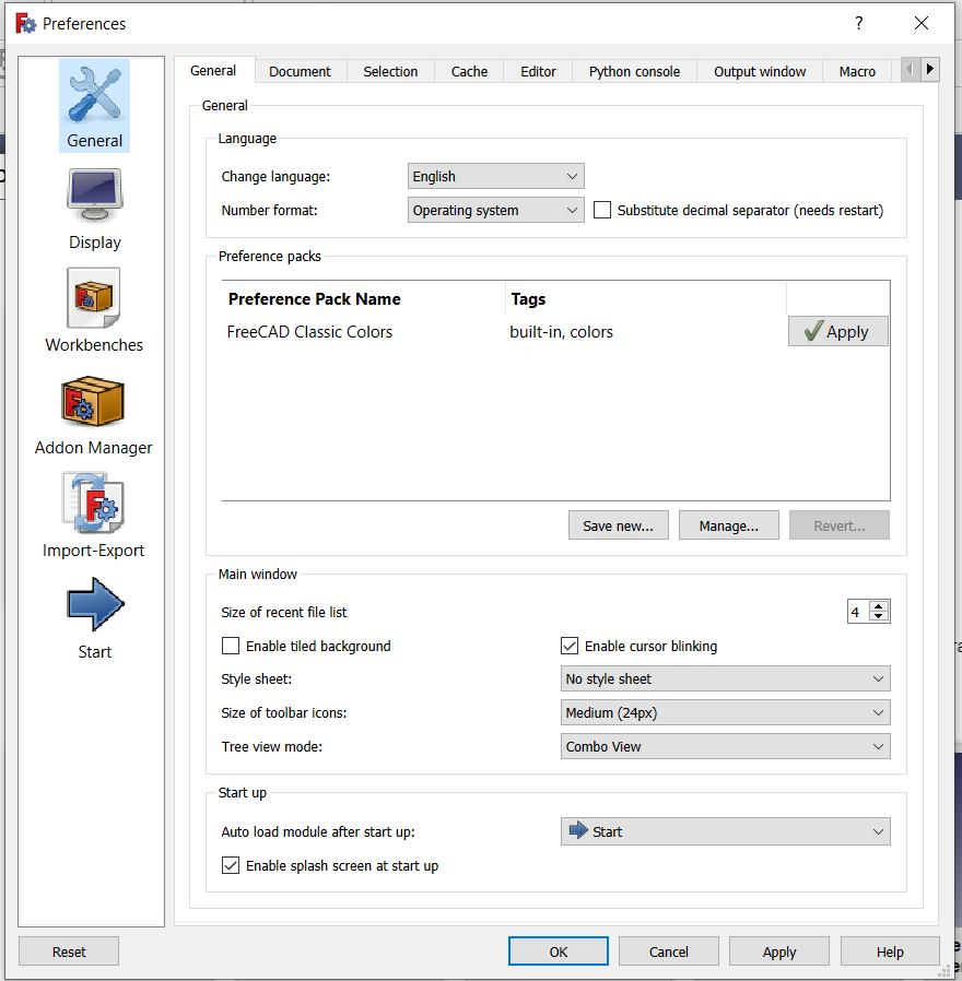
Storage options: As any complex application, FreeCAD might crash from time to time. Here you can configure a few options that will help you to recover your work in case of a crash.
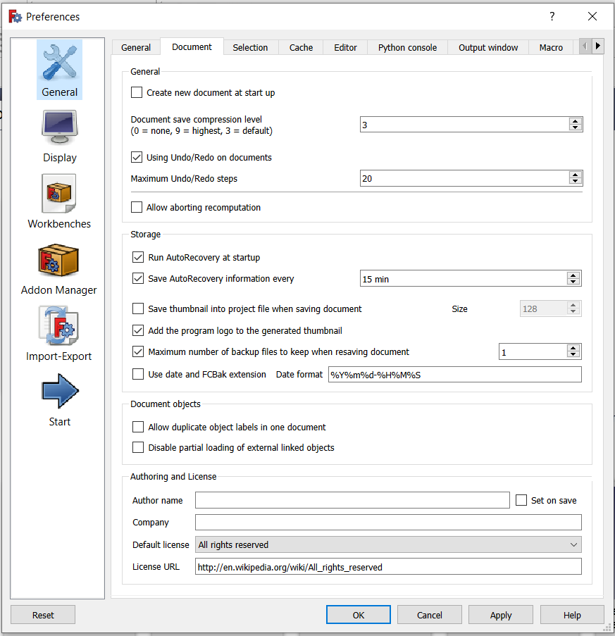 Document – Save AutoRecovery information every (type 10min)
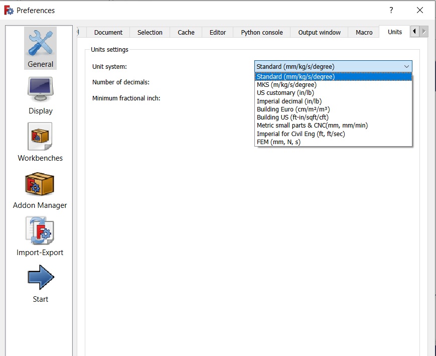
Units: Here you can set the default units you wish to use. It will be easier to work on the examples later, to stay in mm/kg/s/degree.
Change of the colour of the background:
Edit – Preferences-Display-Colors-Color gradient
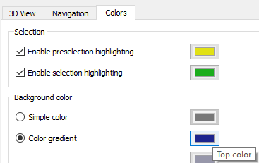
Click on the frame Top color and the new window will be opened in which you can choose the colour of the background.
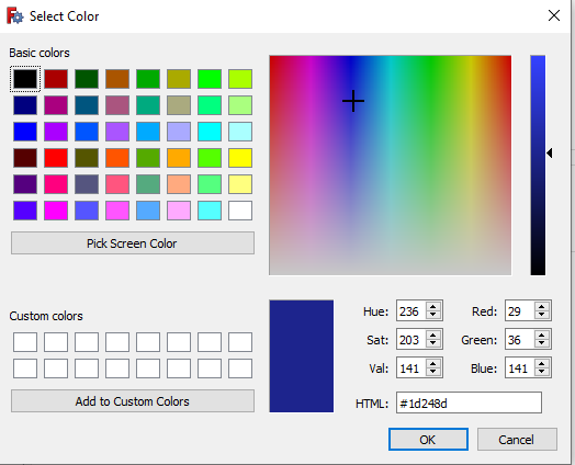
You can choose the colour by scrolling the basic colour and you can choose the shade of the colour vertically.
Lesson 02 – 2D drawing
To create the new FreeCAD document click on File→New.
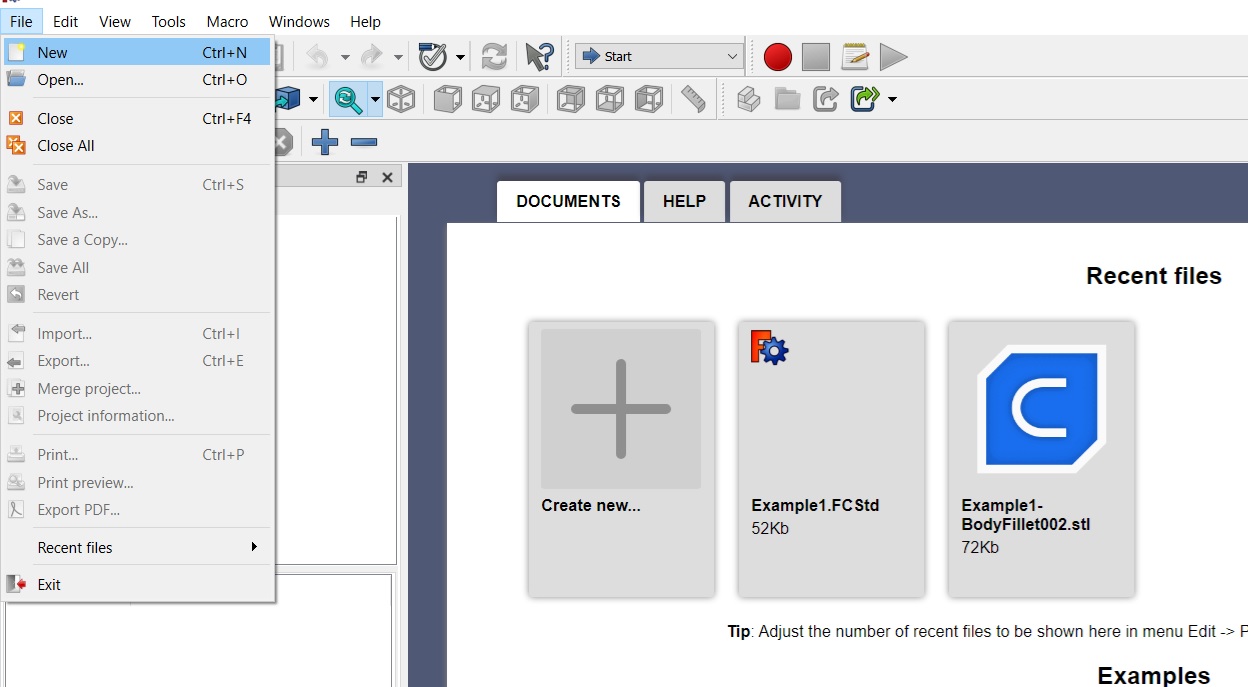
Picture 2-01
After creating new document, it is needed to choose the right navigation. After opening the new document, it is needed to choose the right navigation (manipulation) using the mouse.
By choosing the option CAD, there are different possibilities of navigation (manipulation).
After opening a new document, it is necessary to choose the way of navigation (manipulation) using the mouse.
By opening the CAD tab, various navigation (manipulation) options appear.
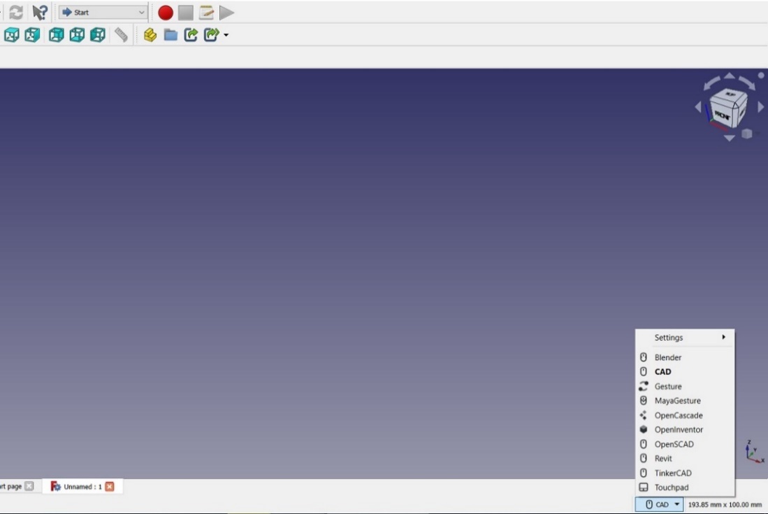
Picture 2-02
We select the Touchpad tab. After opening it, keep the mouse cursor on it so that the Touchpad navigation style appears. We see that there are about 10 styles of navigation. In this tutorial, we will use the Touchpad style of navigation because it can be used by users who only use the Touchpad on their laptops. Here is a pictorial presentation of instructions for selecting, zooming, rotating and moving. Both for operating the touchpad and for operating the mouse.
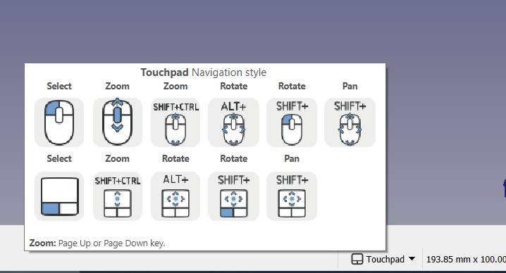
Picture 2-03
In order to test how it practically works, we will draw a simple drawing and practically try out all the possibilities on it.
The procedure for activating the window in which we will draw our drawing is as follows: by clicking on the drop-down menu Start→Sketcher
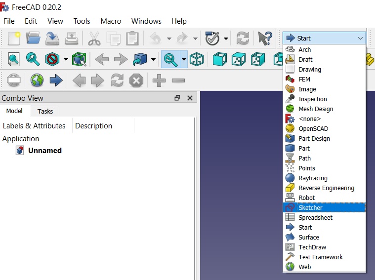
Picture 2-04
By clicking on the Sketcher tab, a number of icons appear, as in the following figure 2-05:

Picture 2-05
By clicking on the menu Sketch→Create sketch
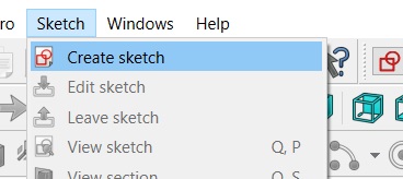
Picture 2-06
The following window appears for selecting the plane in which we want to draw our drawing. Here the XY plane is offered, which we accept by clicking OK.
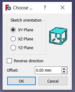
Picture 2-08
As we can see, many of the drawing icons have now become active.

Picture 2-09
Also, a coordinate system with X (red line) and Y (green line) appears, and the center of the coordinate system (red point, hereinafter CCS)
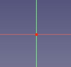
Picture 2-08
First we will draw a circle. By clicking on the circle drawing command ![]() (left click with the mouse, we move away from the center of the circle as much as we want and then left click with the mouse again).
(left click with the mouse, we move away from the center of the circle as much as we want and then left click with the mouse again).
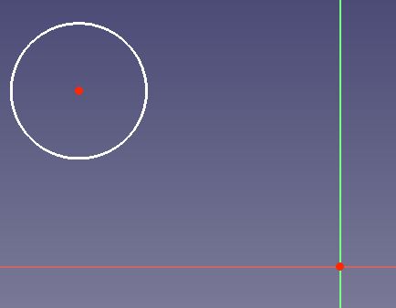 Picture 2-10
NOTE: After drawing a circle, the draw command is still active so we can draw the next circle. When we no longer need it, we turn it off using the ESC key on the computer keyboard or right-clicking the mouse.
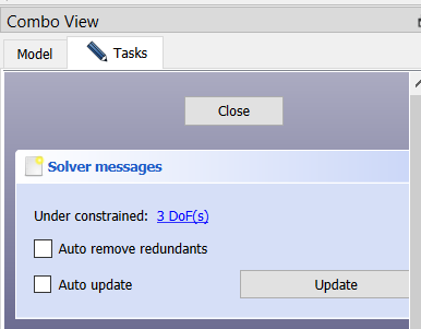
In the left part of the screen in the window Combo View→Solver messages →Under constrained there is a message 3 Dof(s) (degree of freedom), which means that we need to define 3 parameters for our circle: the distance of the center in the X and Y directions and the diameter of the circle.
In the left part of the screen in the window, which means that we need to define 3 parameters for our circle: the distance of the center in the X and Y directions and the diameter of the circle.
Picture 2-11
NOTE: A degree of freedom (DOF) indicates a possible movement of one element. For example, a point can be moved both in horizontal and vertical directions, so it has two degrees of freedom. If a line is defined by two points, therefore in total it has four degrees of freedom. If we fix one of those points, then the entire system has only two degrees of freedom available; if we additionally fix the horizontal movement of the remaining point, we only have one degree of freedom left; and if we also fix the vertical movement of this point, then the last degree of freedom disappears, and the line cannot move from its position any more.
Constraints are “rules” that tell us under which conditions a geometrical object can move and by how much. They are used to eliminate the degrees of freedom so that the sketch has a stable shape. If we eliminate all degrees of freedom, then the sketch is fully constrained, and has a fixed shape, which means that its points cannot move at all. In general, it is a good idea to fully constrain sketches because this will result in stable models.
There are two principal types of constraints:
Geometric constraints define characteristics of the shapes without specifying exact dimensions, for example, horizontality, verticality, parallelism, perpendicularity, and tangency.
Datum constraints define characteristics of the shapes by specifying dimensions, for example, a numeric length or an angle.
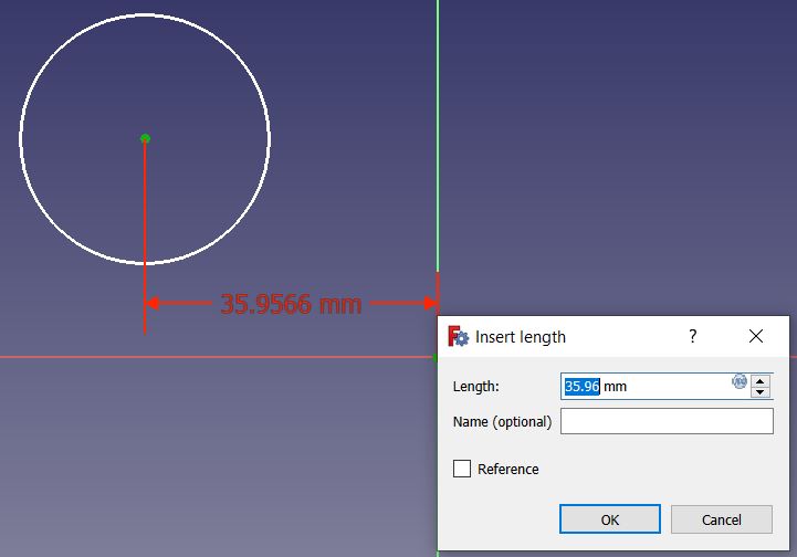
Now we will dimension our circle so that it is completely defined in our workspace. By clicking on the Constrain horizontal distance command ![]() , and then selecting the
, and then selecting the
center of the circle and then selecting CCS, the Insert Length window appears in which we enter the desired value along the X axis (eg 40mm).
Picture 2-12
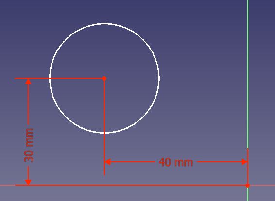
The procedure is repeated to define the center of the circle in the Y direction of the coordinate system using the command ![]() , first select the center of the circle, and then select CCS. Here we can enter a value of 30mm.
, first select the center of the circle, and then select CCS. Here we can enter a value of 30mm.
Picture 2-14
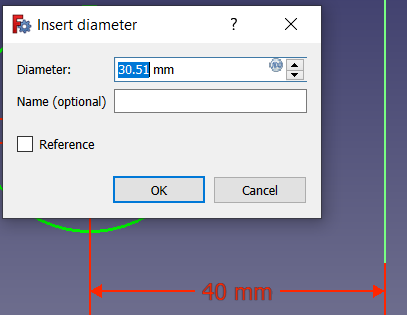
Now we only have to define the diameter of the circle by clicking on the command Constrain arc or circle ![]() , and then by clicking on the circle, after which the window Insert diameter appears, where we enter the desired diameter of the circle, e.g. 45mm (Picture 2-16).
, and then by clicking on the circle, after which the window Insert diameter appears, where we enter the desired diameter of the circle, e.g. 45mm (Picture 2-16).
Picture 2-16
NOTE: If we happen to enter the wrong value for the dimensions or later want to change it, move the mouse pointer to the desired dimension (e.g. the diameter of the circle) until it changes color (turns yellow) and double-click to activate the Insert diameter window in which we enter the desired changes.
NOTE: Another way to change dimensions is by using the Combo View window in which we find the Constraints window. Here we see the 3 dimensions of the circle. By double-clicking on one of them, the Insert window appears again, in which we enter the desired changes. (Picture 2-16a).
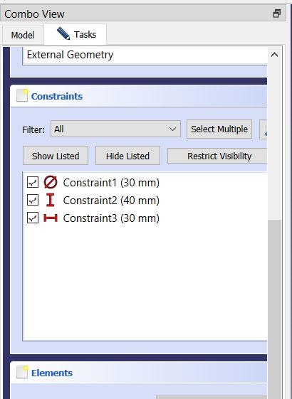
Picture 2-16a
NOTE: Also, if the elevations (dimensions) overlap, we can move them left, right, up, down to make them visible. We also approach with the mouse pointer until the dimension changes color (turns yellow), click on it and move in the desired direction.
NOTE: If you wish to temporarily disable the constraint, you may select it and press Activate/deactivate constraint. When you want to apply it again, press again the same button (Picture 2-16b).
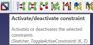
(Picture 2-16b)
In this way, we have completely defined our circle in relation to CCS, and in the window Combo View→Solver messages it is now Fully constrained, which means that the circle, that is our sketch, is completely defined
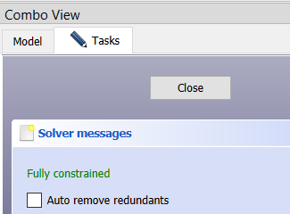
Picture 2-17
Now in the Combo View window, go to Close, which exits the active drawing window and sees our drawing and isometry.
On the right side in the upper corner of the screen (Picture 2-20) we see a navigation cube. By clicking on one of the arrows, we rotate our drawing. We can also click on the page of the cube itself, let’s say the TOP page, to see the view of the drawing in the XY plane in which we drew. Parallel to the rotation of our drawing, the coordinate system that can be seen in the lower right corner of the screen is also rotated (Picture 2-21).
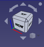

Picture 2-20 Picture 2-21
The commands for the second way of manipulating the drawing are shown in Picture 2-03. By combining the SHIFT, CTRL and ALT keys with the mouse keys, various combinations of selecting, rotating, zooming and moving the drawing are possible depending on our needs. These commands need to be practiced well so that we can set up the drawing or later the 3D model the way we want.
Now, we are going to draw a rectangle measuring 60x40mm, which is 20mm in the X direction from the CCS and 25mm in the Y direction from the CCS. In order to do that, we need to return to the workspace where it is possible to draw. In the Combo View window, activate Sketch by double-clicking (picture 2-22),
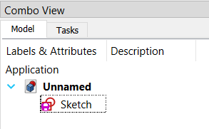
Picture 2-22
and then we use the Create rectangles command, which has several options. We will select the Rectangle option (picture 2-23).
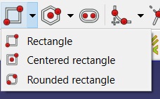
Picture 2-23
Then we draw a rectangle.
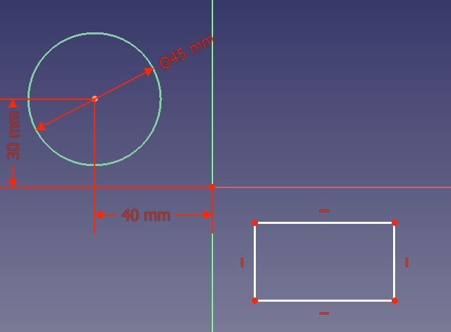
Picture 2-24
In the Combo view window, we see that 4 undefined parameters of the rectangle 4DoF(s) appear (red arrow, picture 2-25).
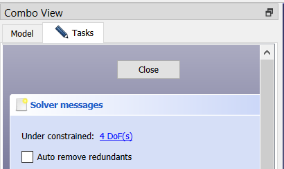
Picture 2-25
These are the following parameters: width and length of the rectangle, position of the rectangle in the X and Y directions in relation to the CCS. Now we will define those parameters with the help of the commands described when defining the circle. When we enter these parameters in the drawing in the Combo View window, the message Fully constrained will appear, which means that we have successfully defined everything.
These horizontal and vertical dashes next to the sides of the rectangle indicate that those sides are parallel to the X and Y axis of the coordinate system.
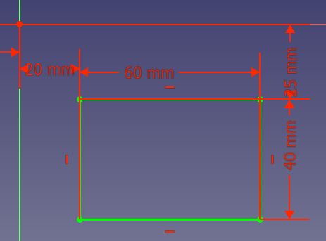
Picture 2-26
Now, we will draw another circle, 30mm in diameter, 30mm away from CCS in the +X direction and 40mm in the +Y direction, but in the new drawing workspace.
The procedure for activating the window in which we will draw our new drawing is described at the beginning of the tutorial (picture 2-04): by clicking on the drop-down menu Start→Sketcher
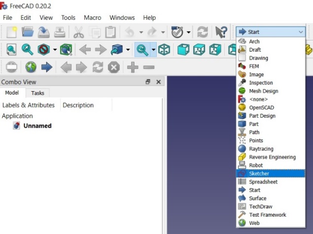
Picture 2-27
Then by clicking on the menu Sketch→Create sketch
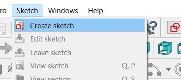
Picture 2-28
A window appears for selecting the plane in which we want to draw our new drawing. Again, the XY plane is offered, which we accept by clicking OK and draw our circle with the given parameters.
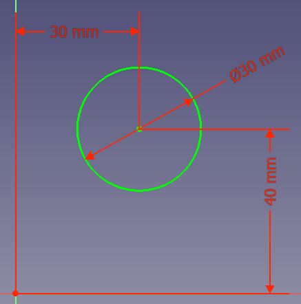
Picture 2-29
NOTE: Here we also use the ESC key on the keyboard to exit some active command, e.g. for horizontal or vertical dimensioning of a circle or for defining the diameter of a circle.
When we have finished drawing our new circle, again in the Combo View window we go to Close, after which we see our two drawing workspaces, Sketches.
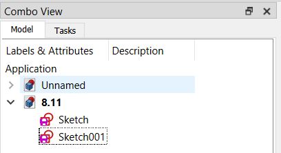
Picture 2-30
In the Sketch workspace we drew our first circle and rectangle, and in Sketch001 we drew our second circle.
With the Fit all command (picture 2-31), we zoom in on all drawings on the workspace, and with the Fit selection command we zoom only the selected Sketch, which we select in the Combo View window (picture 2-33), e.g. Sketch001
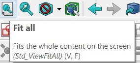
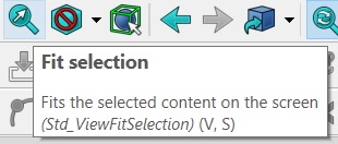
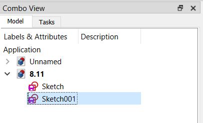
Picture 2-31 Picture 2-32 Picture 2-33
In the Combo View window, by right-clicking the mouse and selecting Rename (picture 2-34), we change the name of our first Sketch to: Circle Fi45mm and Rectangle 60x40mm.
In the same way, change the name of the second drawing, Sketch001 to: Circle Fi30mm (picture 2-35)
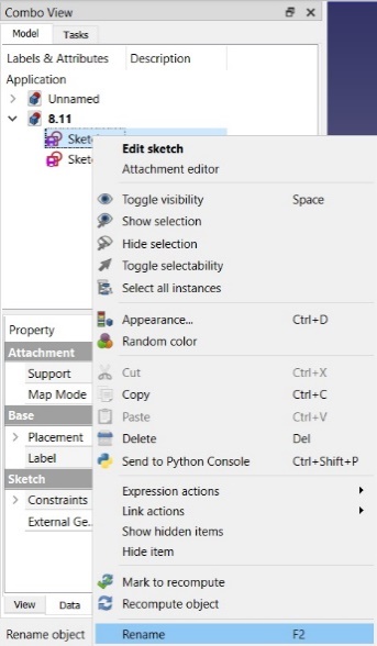
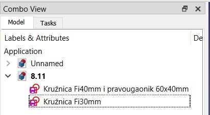
Picture 2-34 Picture 2-35
Exercise task
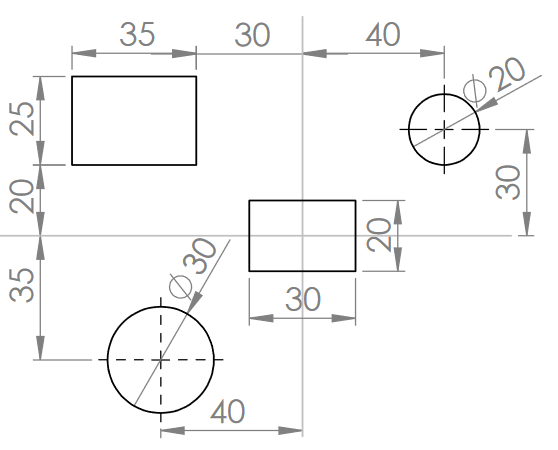
The task is to draw 2 rectangles and 2 circles. Draw the 35x25mm rectangle and the Ø20 circle in Sketch, and the 30×20 rectangle and the Ø30 circle in Sketch001, and then change their names in “Drawing01” and “Drawing02”.
Lesson 3 – 2D drawing: defining constraints, drawing geometric shapes
Now we will draw, a triangle, a pentagon, a circular arc (a quarter of a circle) that intersects a straight line, the use of the rounding commands and the use of the command to draw multiple connected lines
1. We should draw an equilateral triangle, whose side is 20 mm long. This triangle should be 20mm away from the CCS in the -X and Y directions.
We open a new document and, also, we open Sketcher. We select the Create line command and then draw an arbitrary triangle.
Picture 3-01
NOTE: By selecting this command, we notice that the mouse cursor has turned into a white cross. After the first line is drawn, we approach the end point of the first long one with a cross, and then a red cross appears. Then click with the mouse and draw another line. This way we ensure that the lines are connected. Then we move on to drawing 3 lines.
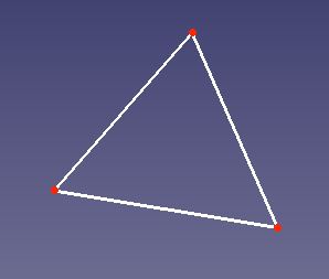
Picture 3-02
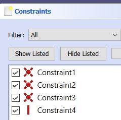
On the left side in the Combo View we see that within the Constrains window we have 3 constraints: Constrains1, Constrains2 and Constrains3
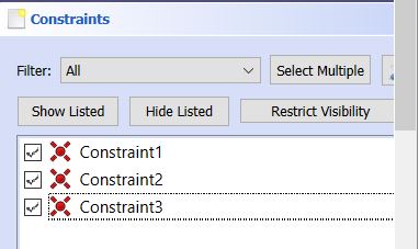
Picture 3-03
By clicking on one of the Constraints, we will see the green theme of the triangle on the triangle. This means that the two longer triangles are joined at that point. In the following case, Constrains1 is selected, which shows the left theme of the triangle. In the Combo View→ Constrains window, we will see all the constraints that we will assign to our drawing.
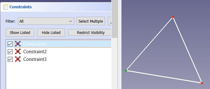
Picture 3-04
The following picture shows the possible limitations.

Picture 3-05
We will explain some of them.
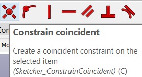 |
 |
 |
| Picture 3-06 | Picture 3-07 | Picture 3-08 |
 |
 |
 |
| Picture 3-09 | Picture 3-10 | Picture 3-11 |
 |
 |
 |
| Picture 3-12 | Picture 3-13 | Picture 3-14 |
Constrain coincident (picture 3-06) – this constraint allows 2 points to coincide. After that, the vertex will move to CCS (picture 3-15). After the tried command, go to Edit→Undo to go back one step.
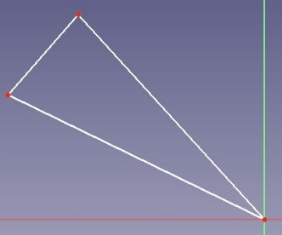
Picture 3-15
We will draw two random lines.
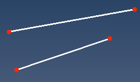
After that, we should activate Constrain coincident by clicking on the right end of the first line, and the clicking on the end of the second line. We will se that our lines joined in one point.
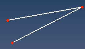
NOTE: The point that was selcted first will be fixed, and the second point will be fixed to the first one.
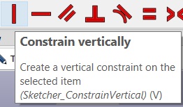
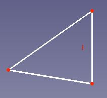
Constrain verticaly – setting the vertical limit of a line (picture 3-7). Select the command, then click on the right side of the triangle. We notice that it has become vertical and that there is a small red line next to it that indicates verticality. We can see that in Combo View→ Constrains (picture 3-17). By clicking on Constraint 4, the small red line indicating verticality will turn green. After the tried command, go to Edit→Undo to go back one step
. 
Picture 3-16 Picture 3-17
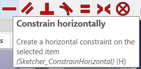
Constrain horizontally – setting the horizontal limit of a line (picture 3-8).
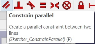
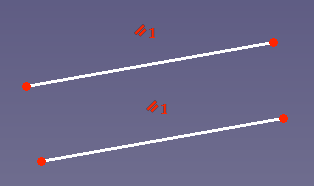
Constrain parallel – setting parallelism constraints (picture 3-9). We use this constraint when we want two lines to be parallel.
Picture 3-17a
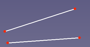
We will draw two random lines. Click on Constrain parallel ![]() , then click on those two lines. The lines will become parallel.
, then click on those two lines. The lines will become parallel.
Picture 3-17b
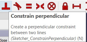
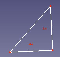
Constrain parpandicular – setting the perpendicularity constraint (pictures 3-10) when we want 2 lines to be at an angle of 90 degrees. In the following picture, we see that the bottom and right sides of the triangle are perpendicular (picture 2-18).
Picture 3-18
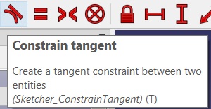
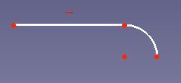
Constrain tangent – setting the tangency constraint (picture 3-11) when we want, for example, a longitudinal and a circular tangent (picture 3-19).
Picture 3-19
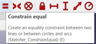
Constrain equal – setting an equality constraint (picture 3-12) when we want two or more lines, circles or any geometric shapes to be equal.
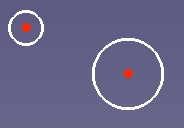
We will draw 3 random circles like the ones on the picture.
Picture 3-19b
You should click on the command Constrain equal ![]() . Then click on the first circle and after that on the second one.
. Then click on the first circle and after that on the second one.
NOTE: The dimensions of every next cirlce will depend on the circle we selected first.
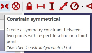
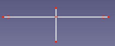
Constrain symmetrical – setting a symmetry constraint (picture 3-13) when we want, for example, 2 points of length (or length) to be at a symmetrical distance in relation to the given length. Picture 3-20 shows that by using this command, the vertical length became the bisector of the horizontal length. The procedure is as follows: we first select one point of the horizontal length, then another and finally the vertical length and then the command Constrain symmetrical.
Picture 3-20
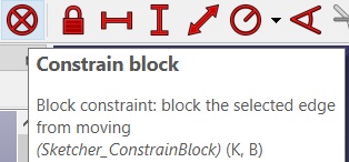
Constrain block – setting the limitation of fixing one or more lines (picture 3-14). After using this restriction, it is not possible to move selected lines or geometric shapes.
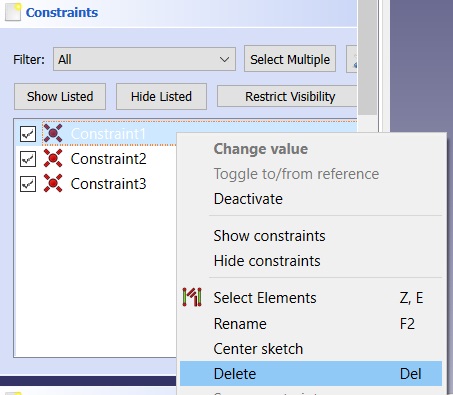
NOTE: All the constraints we set can be seen in Combo View→ Constrains. If we no longer need a restriction, select it by right-clicking the mouse and then Delete in the menu that appears. (picture 3-21).
Picture 3-21
Now we can draw our equilateral triangle, whose side is 20mm long. This triangle should be 20mm away from the CCS in the -X and Y directions. For the lower side of the triangle, set the limit that it is horizontal, and all three sides should be equal (20mm each). The triangle should look like the following picture.
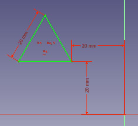
Picture 3-22
In this way we learned the use of some restrictions. We could have drawn our triangle very easily using the command Sketch→Sketch geometries→Create equilateral triangle
2. Now we are going to draw a pentagon in the XY part, whose bottom side is horizontal, and its sides are 15mm each. Distanced from CCS by 20mm in the direction of the X and Y axes. To select the pentagon drawing command, go to Sketch→Sketch geometries→Create pentagon. (picture 3-23). As we can see, here are the commands for drawing all the geometric shapes we need: point, line, circle, circular arc, ellipse, hyperbola, rectangle, square, etc.
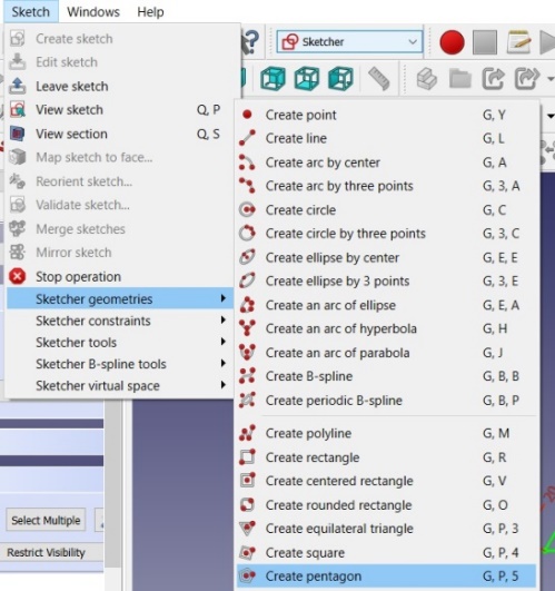
Picture 3-23
The drawing should look like the picture 3-24.
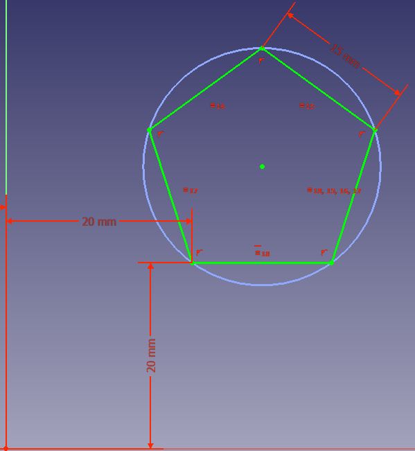
Picture 3-24
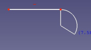
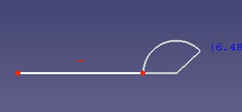
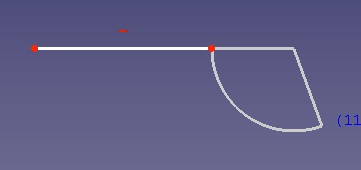
3.Our next drawing is a circular arc (a quarter of a circle) that creates a tangent with a straight line in the –X-Y part of the coordinate system. The drawing should look like the following image.
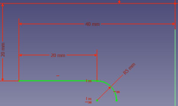
Picture 3-25
The procedure is as follows: we draw along 20mm, the beginning of which is 40mm away in the -X direction, 20mm in the -Y direction. Then Sketch→Sketch geometries→Create arc by center.
We click under the right end of the length and use the cross to approach the right end of the length. When the red cross appears, we click so that our circular arc is connected to the longitudinal one. Then we draw about a quarter of the circle. To make sure it’s the right quarter, we have to introduce restrictions by clicking on the center of the circle and the right point of the circle and then on the horizontal limit. Then, left click with the mouse or ESC on the keyboard to exit the command.
By clicking on the center of the circle and the upper point of the circle and then on the vertical constraint.
Now we are sure that there is a quarter of the circle in the pie. And to make sure that the tangent is along, we will also introduce the Constrain tangent constraint. We click on the length and then on the circular arc and then on this boundary. Then OK to the pop-up notification window and that’s how we finish our drawing.
4. Using the rounding commands
We draw a 60x40mm rectangle that is 20mm in the direction of the X axis and 30mm in the direction of the -Y axis.
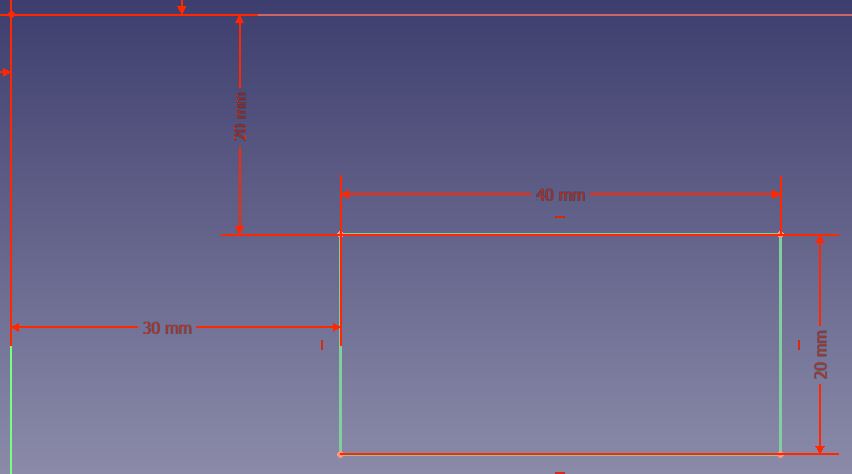
Picture 3-26
Here we have two rounding commands: Sketch fillet i Constraint-preserving sketch fillet
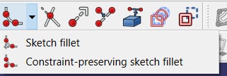
Picture 3-27
We will round the upper left corner of the rectangle first with one command and then with another command to see the difference. We first activate the Sketch fillet and then select the left and upper sides of our rectangle. We will get a rounding like in the next picture.
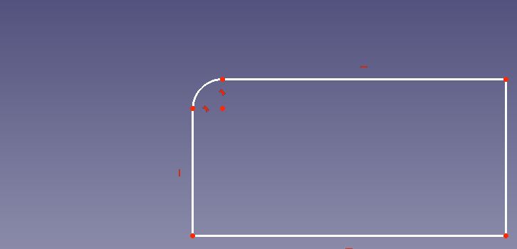
Picture 3-28
Now we go back a step Edit→Undo, then select the second command Constraint -preserving sketch fillet and repeat the process. We will get rounding as in picture 3-29.
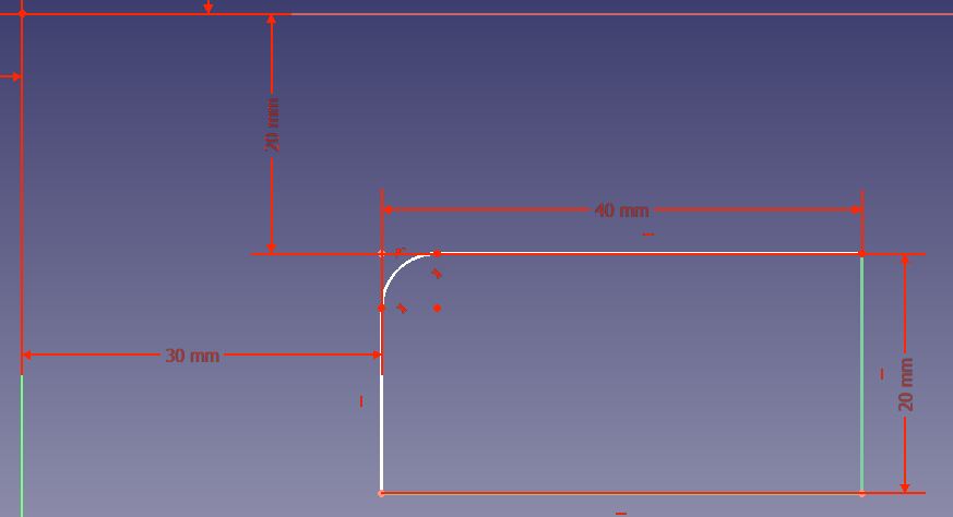
Picture 3-29
We notice that by using the second command, we saved all the dimensions of our drawing, as the name of the command suggests.
We will now define dimensions for the arc using the command Constrain arc or circle ![]() and we will type in the value of 10mm. Then, we will draw another arc using the same command with the dimension of 8 mm as it can be seen on the picture.
and we will type in the value of 10mm. Then, we will draw another arc using the same command with the dimension of 8 mm as it can be seen on the picture.
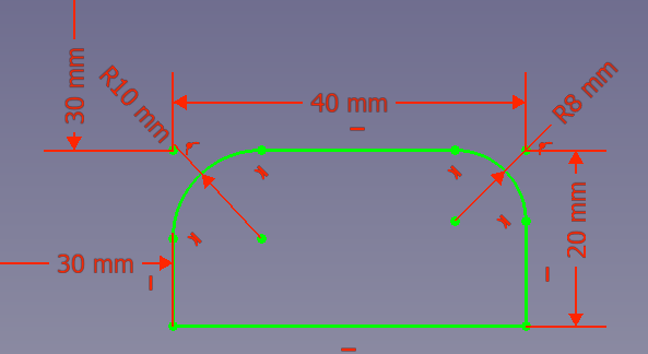
Picture 3-29.2
On the left side in the Combo View window, we can see that our drawing is totally defined by dimensioning both arcs (Fully constrained).
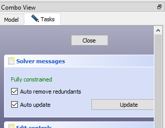
Picture 3.29.3
5. Using the command to draw multiple connected lines – Create polyline
This command is very useful for drawing, especially using the magic letter M on our computer keyboard. We activate it with Create polyline.
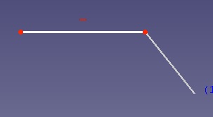 |
 |
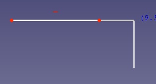 |
| Activating command | Pressing a key M, the first time | Pressing a key M, the second time |
 |
 |
 |
| Pressing a key M, the third time | Pressing a key M, the fourth time | Pressing a key M, the fifth time |
Picture 30
- By activating the command after the drawn line, we draw the next line arbitrarily at any angle
- By pressing the M key for the first time, we draw a parallel line in the first one that is joined by a cross line
- By pressing the M key a second time, we draw a straight line tangential to the first and perpendicular to it
- By pressing the M key a third time, we draw a tangential circular arc that is connected to the first one
- By pressing the M key for the fourth time, we draw a circular arc normal to the previous line on the left
- By pressing the M key for the fifth time, we draw a circular arc normal to the previous line on the right
- Korišćenje komande za isecanje linija – Trim edge
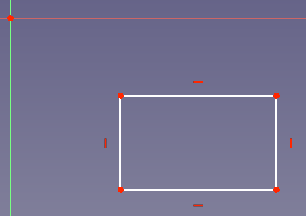
You need to make a drawing which is similar to the one on the picture with constraints so that lines are horizontal and vertical.
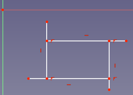
After that you need to activate the command Trim edge ![]() and to select the lines apart from the rectangle like on the picture. Then click on each line to erase them because they are not needed. After that, there should be only only rectangle on the picture.
and to select the lines apart from the rectangle like on the picture. Then click on each line to erase them because they are not needed. After that, there should be only only rectangle on the picture.
- Using the command for extending the lines- Extend edge
It is needed to draw 2 lines as similar as it is shown on the picture with the constraints to be horizontal.
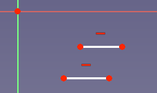
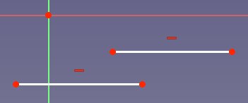
After that we can activate the command Extend edge ![]() and we should select the first line, click on it and then move the cursor to the right in order to extend it. After that, click once more in order to finish elongating the line. We should do the same with the second line but it should be elongated to the X-axe. The lines should look as it is shown on the picture.
and we should select the first line, click on it and then move the cursor to the right in order to extend it. After that, click once more in order to finish elongating the line. We should do the same with the second line but it should be elongated to the X-axe. The lines should look as it is shown on the picture.
8. Using the command for spliting lines- Split edge
You need to draw one line like it is on the picture with the contraint for the horizontal line.
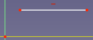
Next, activate the command Split edge ![]() , move cursor to the line, click anywhere on it, and then move cursor to the right. After that click on the line and repeat the action once again. The line should be devided on 4 lines like on the picture.
, move cursor to the line, click anywhere on it, and then move cursor to the right. After that click on the line and repeat the action once again. The line should be devided on 4 lines like on the picture.
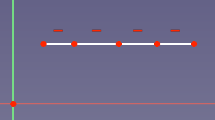
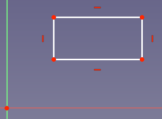
As you can see these is still the horizontal constraint. If we erase these constraints and add new ones, such as vertical contraints in two lines, it is possible to make the rectangle from the first line.
Task for exercising
It is necessary to make a drawing as in the following picture. Make sure that point W on the drawing coincides with CCS.
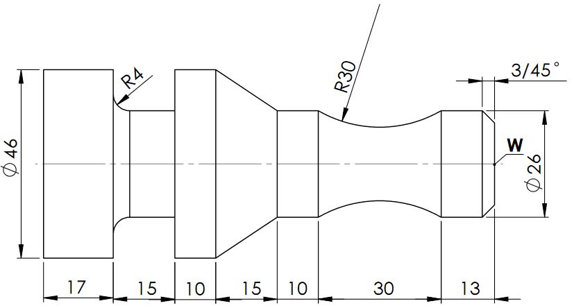
Picture 3-31
Make your own example of a drawing for the object of your choice.
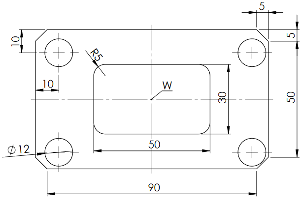
Task for exercising
You should make a drawing as it is shown on the picture. Take care that point W on the drawing coincides with CCS.
Lesson 4 – 3D model: Prismatic parts
From the drop-down menu, select Part Design
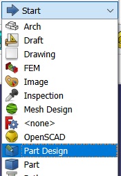
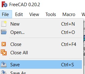
Then we Save our future file.
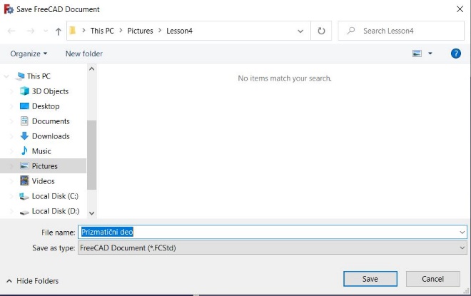
We give a name to our future model. For example, Prismatic part.
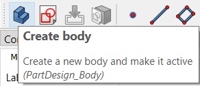
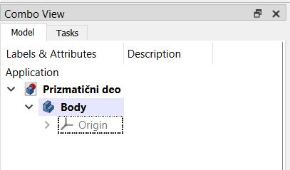
We click on the Create body icon.
We can see an active icon Body in the Combo view window.
Now, we choose Create sketch
We select the desired plane either in the Combo view window or on the desktop by selecting the desired plane (Shift+LCM key by moving the mouse to rotate the plane).
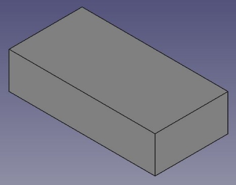
We choose the XY plane in which we will make our drawing. We will draw a rectangle with dimensions 100x60mm whose center coincides with CCS.
Select the Centered rectangle command and then draw our rectangle.
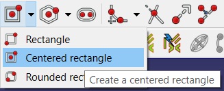
We start drawing from the center of the coordinate system so that the center of the rectangle coincides with the center of the coordinate system (red point, hereinafter CCS). After drawing, we add the desired dimensions to our drawing.
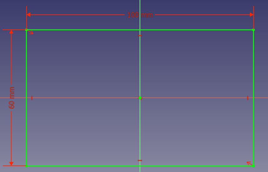
We can see that the drawing is green after dimensioning which means that it is fully defined.
We click on Close in the Combo View window, then right click on Sketch→Rename to change the name of our drawing to “Rectangle”.
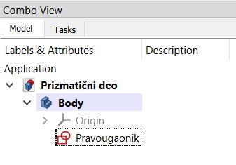
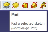
To get a 3D prismatic model from our drawing, we use the Pad command
We see that the Pad parameters window appears in the Combo View window where we can change various parameters of our 3D model.
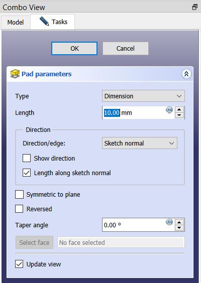
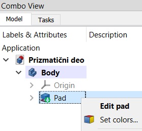
In Length, enter 30mm and left click on the mouse outside the Combo View window to see the change. If we press Enter on the keyboard, we exit the Pad parameters window. If we want to make some changes to our 3D model, in the Combo View use right click of the mouse, go to Pad→Edit pad.
Now we can again change the parameters according to our model’s wishes
We click on Enter or OK in the Combo View window when we finish the changes. In order to see where our 3D model is in the coordinate system, we need to make it visible. We do it as follows: we select Origin and then press the Space button on the keyboard.
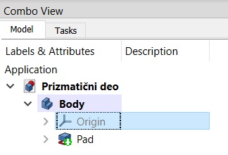
We can see that all 3 planes (XY, XZ, YZ) have become visible.
In order to understand the possibilities of changing the parameters, activate the Pad parameters window again (right click on Pad→Edit pad). After experimenting, we return to our model.
If we want to change something on our model regarding the dimensions of the basic drawing, we do it as follows:
By clicking on the arrow to the left of Pad, our basic drawing “Rectangle” appears. 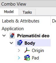
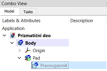
Right click to the Rectangle and then Edit sketch.
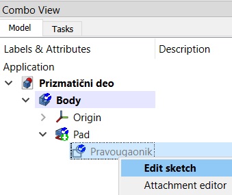
Now we can change our basic drawing based on which we get a 3D model. We will change the width of the rectangle to 120mm (we move the cursor to the dimension, when it turns yellow we should do the left double-click on the mouse, change the dimension and choose OK).
By pressing Close in the Combo View window, we close our Sketch “Rectangle” and see that our 3D model has also changed. It is now 120x60x30mm.
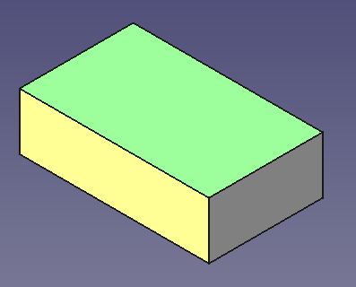
Now we are going to create 2 circular pockets on the 3D model. Let’s check that we are in Part Design mode, and then select the upper surface of the 3D model
Then we choose Create Sketch
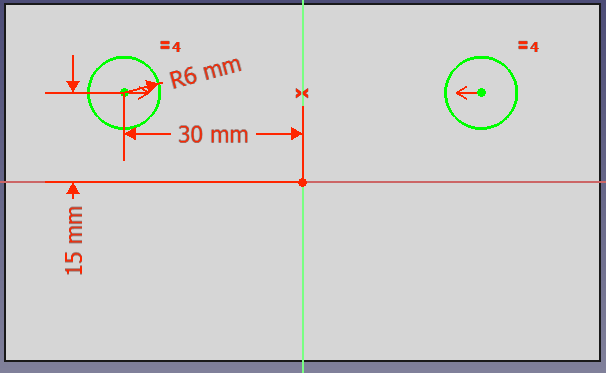
Now we draw 2 circles on the selected surface as in the following image, 30mm and 15mm away from CCS, diameter 12mm
Choose Close in the Combo View window, and then select the Pocket command.
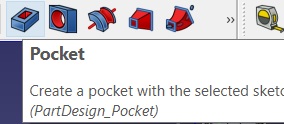
A new Pocket parameters window appears in which we have various options for changing the parameters of our 2 circular pockets.
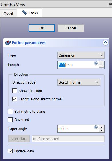
Enter dimension 5mm in Lengh and press OK in the Combo View window. In this way we created 2 circular pockets on our model.
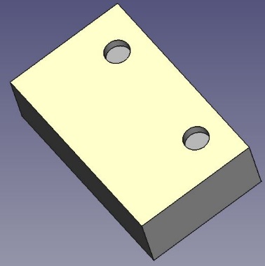
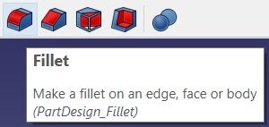
Now we will fill the 4 vertical edges of our model using the Fillet command.
We first select the four vertical edges of our model. Press the Ctrl key on the keyboard and use the left click on the mouse to select one edge at a time while rotating the model. When we have selected all 4 edges, click on the Fillet command
A new window Fillet parameters appears.
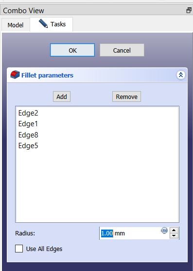
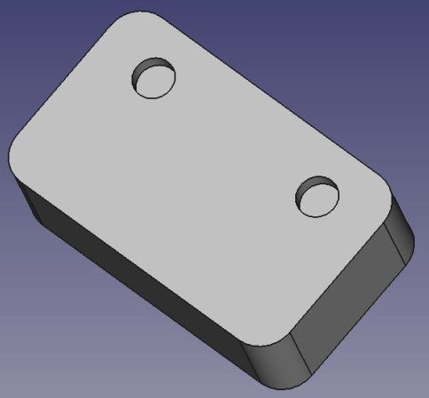
Enter 10mm in Radius, then press OK. In this way, we rounded the selected edges.
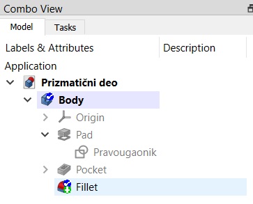
If we want to make some changes to the model, let’s say that the upper 2 edges are not rounded in the Combo View window, by double-clicking on Fillet, we activate the Fillet parameters window again.
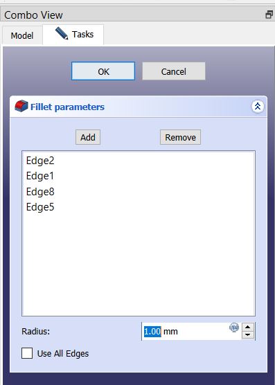
In this window, we select the edges in the next order: Edge2, Edge1, Edge8 and Edge5 to determine which are the upper edges (the selected edge is green on the model). When we determine which 2 edges are the top, we delete them by pressing the Delete key on the keyboard.
By deleting those 2 edges, our model should now look like the following image:
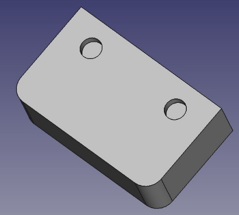
Now we will tilt the 2 top vertical edges of our model using the Chamfer command.
First, select the upper edges, then activate the Chamfer command.
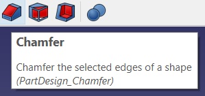
A new window Chamfer parameters appears.
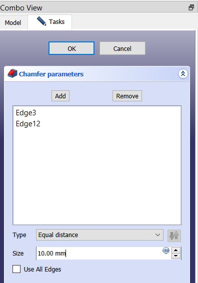
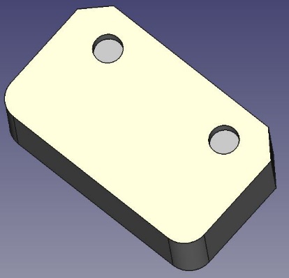
In Size, we enter a value, e.g. 10mm and click on OK. Now our model should look like the following image:
Now by double-clicking Chamfer in the Combo View window, we activate the Chamfer parameter again.
In the Chamfer parameter→Type window, we notice different possibilities for cutting edges.
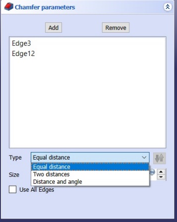
Here we should experiment a bit with these possibilities.
Exercise task
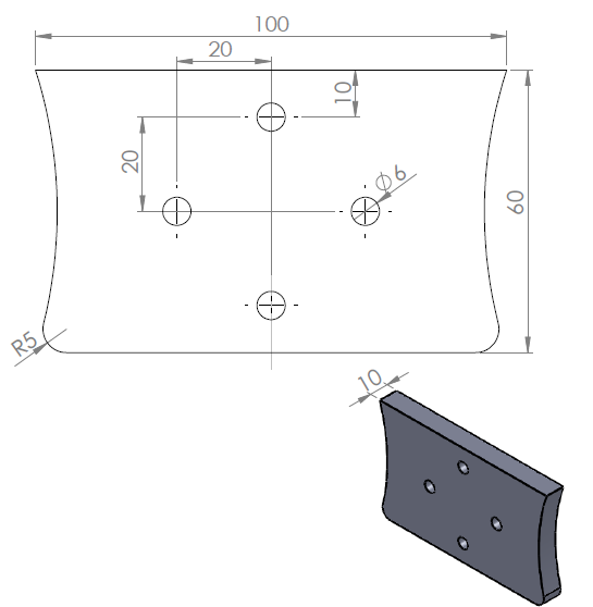
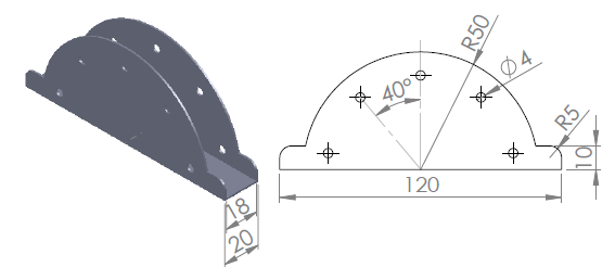
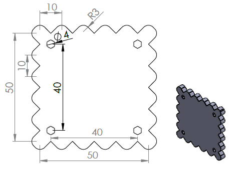
Lesson 5 – 3D model: Axisymmetric parts
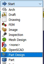
From the drop-down menu, select Part Design
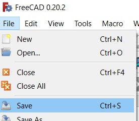
Then we Save our future file.
We give a name to our future model. For example, axisymmetric part.
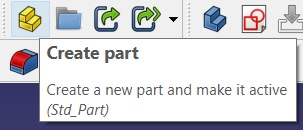
We click on the icon Create part.
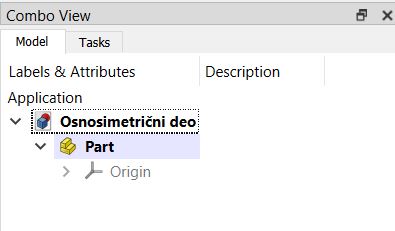
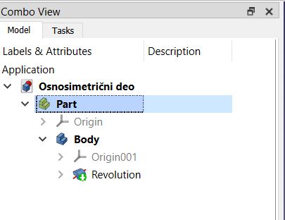
Now, we can see an active icon Part in the Combo view window.
Select Part, then activate the command Create Body.
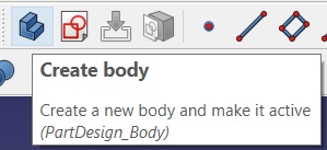
After that we activate the command Create Sketch.
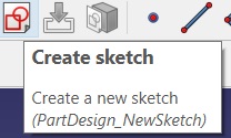
We select the desired plane either in the Combo view window or on the desktop by selecting the desired plane (Shift+left click on the mouse key by moving the mouse to rotate 3 planes).
Here we do not choose the XY plane as when drawing prismatic parts, but the XZ plane in which axisymmetric parts are drawn.
We will now draw a drawing as in the following picture. CCS is in the lower left corner.
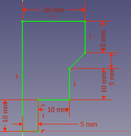
Then choose Close.
Then, we select the command Revolution
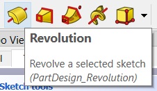
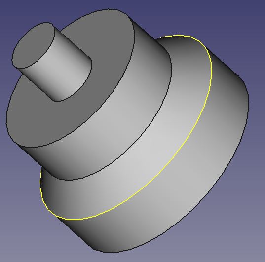
After that our axisymmetric 3D model appears as in the following image:
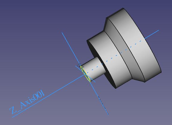
NOTE: When drawing axisymmetric parts, it is very important to select the XZ plane when drawing the sketch, so that the axis of symmetry coincides with the Z axis, both for printing on a 3D printer and for making such parts on CNC lathes.
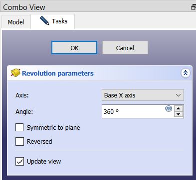
We can see that Revolution parameters has opened in the Combo View window.

Here we can change, for example, the angle of rotation around the Z axis, e.g. 270º and we will get the following model:
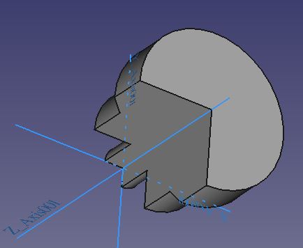
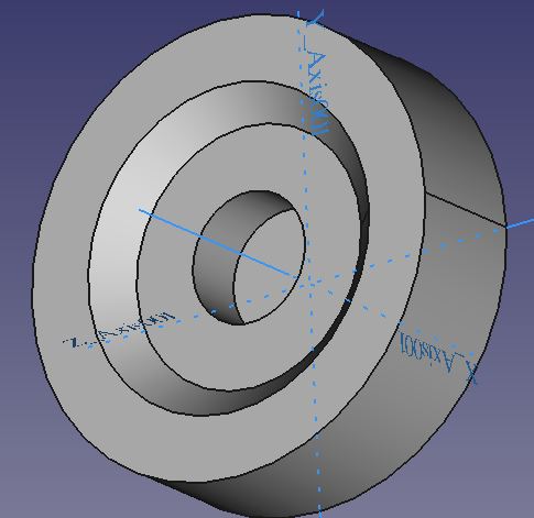
Or change the axis of rotation of our sketch e.g. Base X Axis (rotating our sketch around the X axis)
So we get a model like in the next sketch:
The possibilities are different, but let’s go back to our required 3D model where the axis of rotation is the Z axis.
Now,let’s select Part in the Combo View window,
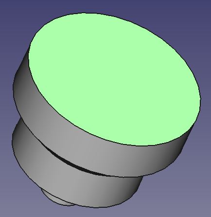
Then we select the surface on which we want to draw, which is the upper surface,
And then we choose Create sketch.
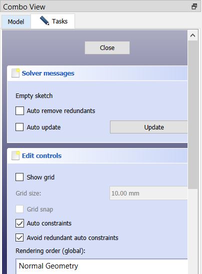
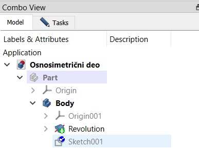
Then, in the window Combo View we choose Model
Then, double click on Sketch001
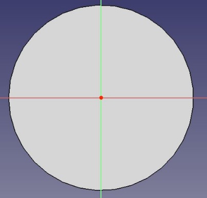
Now we have the opportunity to draw on the selected surface
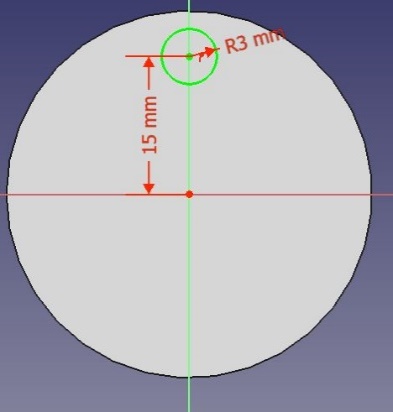
We draw a circle as in the following picture:
Then, choose Close in Combo View window.
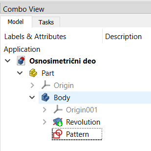
Afterwards, we will rename Sketch001 into Pattern
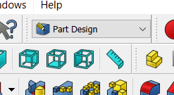
We will check if Part Design is active
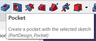
And select the command Pocket
A new window opens in the Combo View window, Pocket parameters.
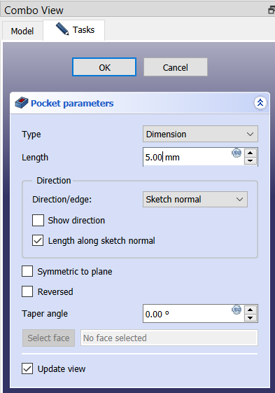
Here we adjust the depth of the pocket, e.g. 5mm (Length) and the angle at which our pocket is hollowed out e.g. -20º (Taper Angle). Then click OK.
Our pocket should look like the one in the following picture:
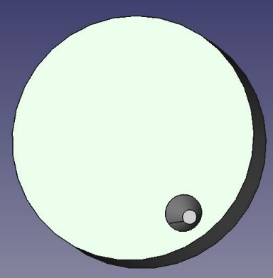
We can see that the bottom of the pocket is hollowed out at an angle of 20º.
In order to copy this pocket in a circle, first select the side of the pocket so that it turns green.
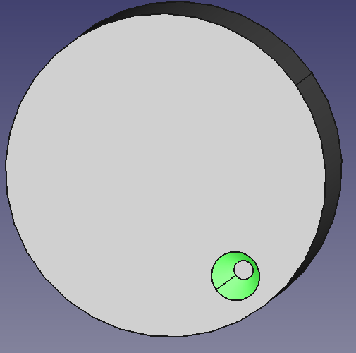
Then click on the command Polar Pattern
And then a new window opens in the Combo View window, Polar Pattern parameters
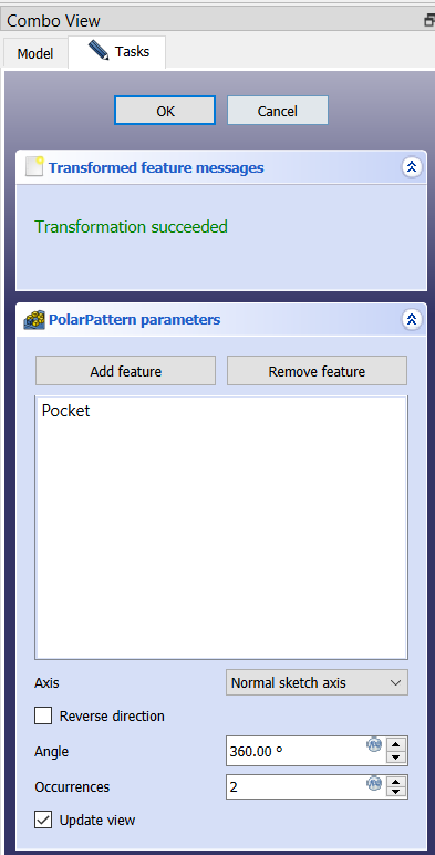
In this window, we can now change the angle. If, for example,it is 360º, the pocket will be copied around the entire circle. Also, here we determine the total number of pockets (Occurrences). Let’s fill in with number 5, then click OK. We can see that we have 5 pockets evenly distributed.
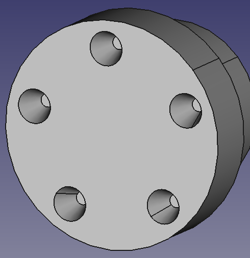
The Linear Pattern command is used in a similar way. First, in the Combo View window, delete the Polar Pattern (RCM→Delete). Let’s press button 2 on the keyboard to have a TOP view. Now select the pocket and activate the command
After which a new window Linear Pattern parameter appears in the Combo View window.
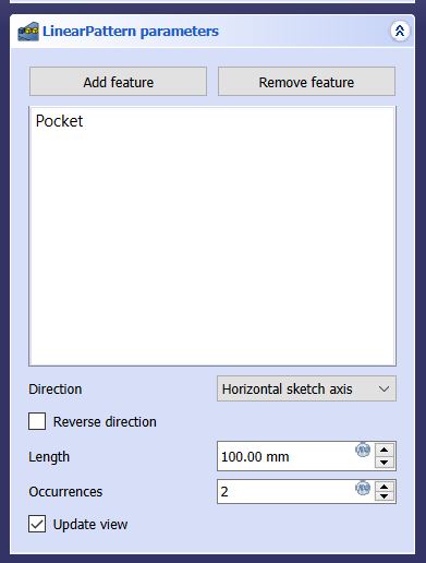
In the Length field, we define the distance at which the pockets will be multiplied (enter, for example, 30mm), and in the Occurrences field, where it is shown the total number of pockets (enter, for example, 5). In Direction, there is a drop-down menu in which we choose the direction in which the pockets will be multiplied.
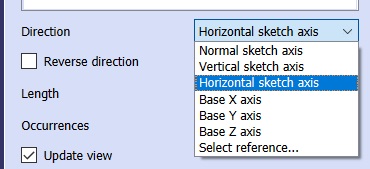
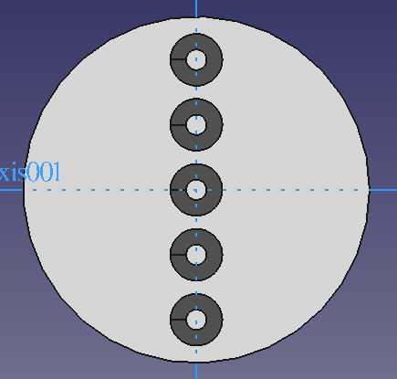
Here we select the Vertical sketch axis, and check the Reverse direction so that the copies of the pocket go up, then click OK in the Combo View window. Now the linearly multiplied pockets should look like the following image:
The command Mirrored is used in a very similar way:
By activating the command, a new window Mirrored parameters opens:
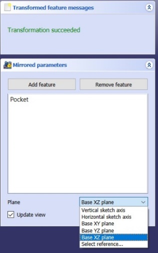
In the window within the Plane drop-down menu, we choose around which plane or axis the pocket will be copied.
Exercise task
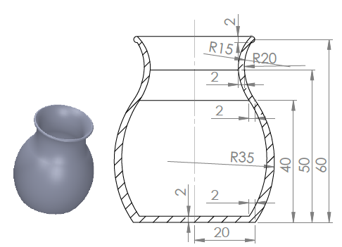
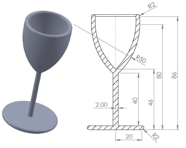
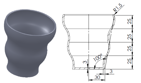
Lesson 6 – 3D model: Creation of typical shapes by pouring sections (Loft)
We will create a new document and save it, giving it a name as desired.
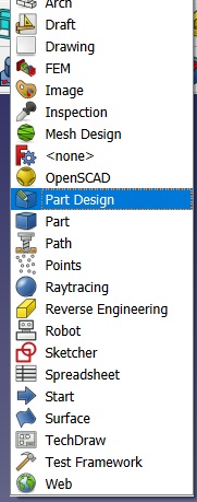
Let’s go to Part Design
and Create part
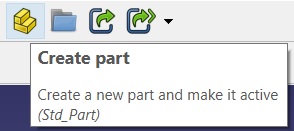
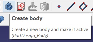
And then, Create body
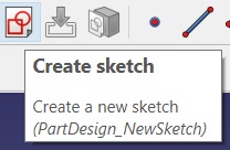
Then choose Create Cketch
Select XY plane, and click OK.
Now we draw a rectangle with dimensions 100x60mm whose center coincides with CCS.
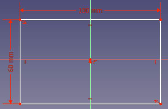
Then we choose Close.
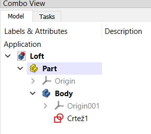
In the Combo View window, change the name of our Sketch to Drawing1 (RCM→Rename→Drawing1),
Now we will create another drawing→Create Sketch
Select XY plane, and click OK in Combo View window.
We can see that our previous drawing – the rectangle – is not visible on the desktop. In the Combo View window, click on Model
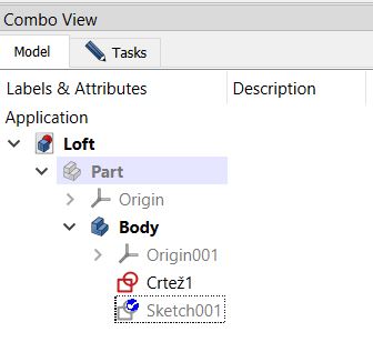
Here we notice that Part is inactive. Select it, then press SPACE on the computer keyboard to make it active. Now our drawn rectangle appears.
We change the name of Sketch001 to Drawing2, select it, and then return to the Tasks window in the Combo View window.
Now we draw a 30x30mm square.
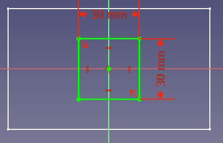
And then choose Close.
Now we need to move this square in the Z direction to the desired distance, e.g. 60mm.
Select Drawing 2, then in the window below, in the Attachment Offset frame, click on the arrow > in front of Position
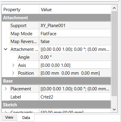
A new possibility for changing the Z distance opens up.
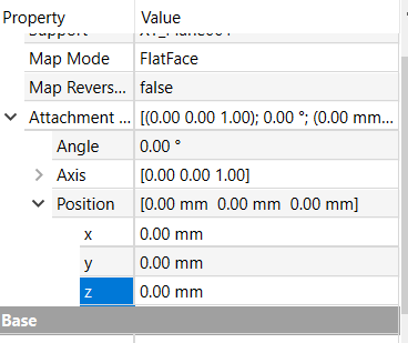
Now click on 0.00mm next to the Z direction and enter a value of eg 60mm.
We see that our square has moved by 60mm in the direction of the +Z axis.
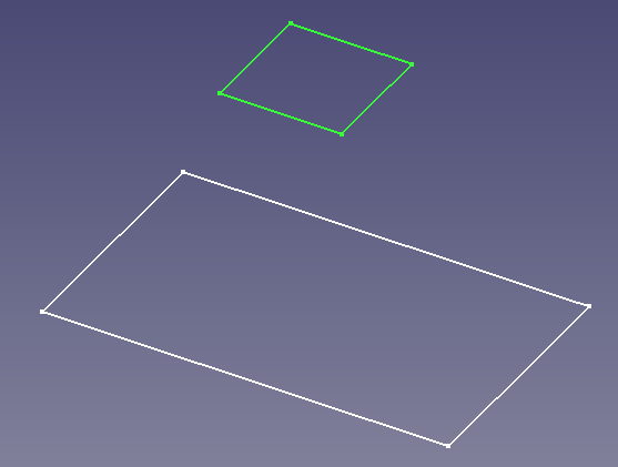
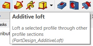
Now select Drawing1, then activate the command
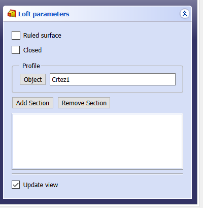
Then, in the Loft parameters window, click on Add Section and select a square in the workspace.
Now we have our 3D model obtained by merging the intersections of rectangles and squares.
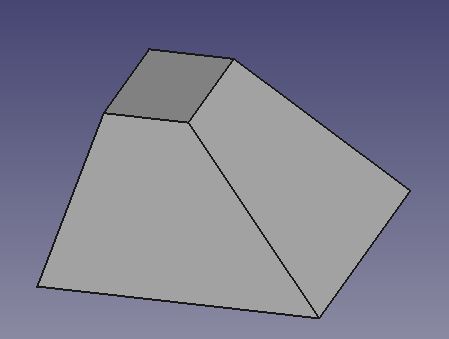
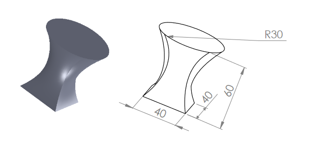
Exercise task
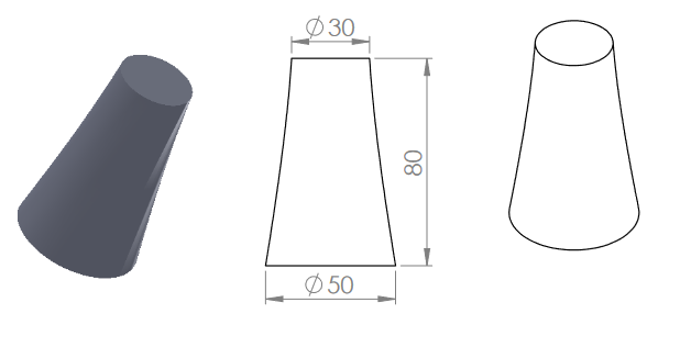
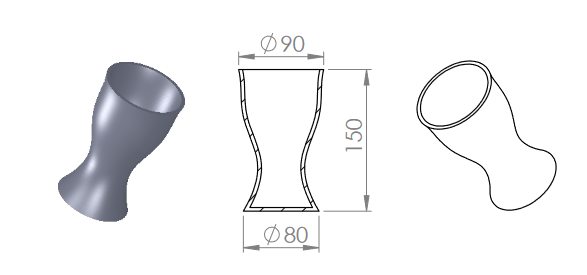
Height of plane: XY, 50, 100, 150mm
Diameter: 80, 50, 100, 90mm
Thickness: 3mm
Lesson 7 – 3D model: Creation of typical shapes by drawing along a curve (Additive pipe)
We create a new document and save it, giving it a name as desired (Additive pipe)
Let’s choose Part Design
and Create part
And then Create body
Then click on Create Cketch
Select XY plane, and then choose OK.
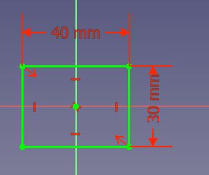
Now we will draw, for example, a rectangle with dimensions 40x30mm whose center coincides with CCS.
Then we click on Close.
In the Combo View window, change the name of our Sketch to Rectangle (RCM→Rename→Rectangle),
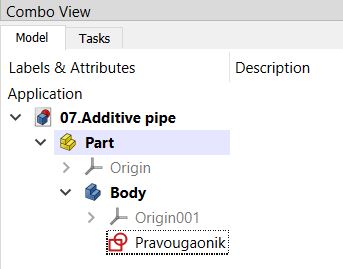
Now we are going to create another drawing: select Body→Create Sketch
Choose YZ plane, and then OK in Combo View window.
Choose B-spline by control points

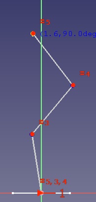
And then we draw a broken line approximately as in the picture, then Esc on the keyboard or RCM.
The bottom white line is actually our rectangle but in the XY plane (now we are in the YZ plane).
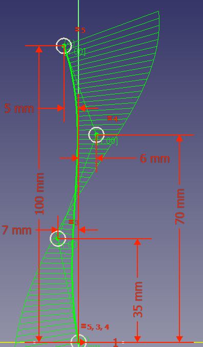
Then we dimension these three points as in the following picture.
So Close in the Combo View window.
Now we see both a rectangle in the XY plane and a curved line in the YZ plane. Rename Sketch001 to Curved Line.
Select the Rectangle drawing in the Combo View window and activate the Additive pipe command
We notice that a new window has opened.
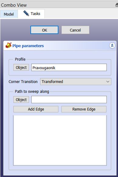
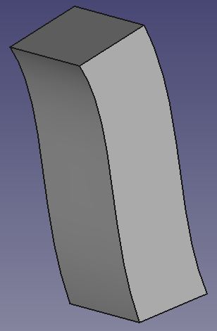
In order to move the selected rectangle along our curved line, we click on Add Edge and then select the curved line in the workspace, then click OK in the Combo View window and we get our 3D model as in the following image.
If we want to convert one shape along the line into another, we will need another drawing. We select Additivepipe and activate another Sketch
Now,we select the XY plane and OK in the Combo View program. Then we draw a circle with a diameter of 30mm.
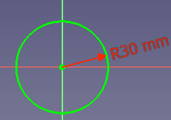
Then Close in the Combo View window. Rename Sketch002 to Circle. We move this circle in the Z direction by 100mm, which is the length of our curved line.
We select Circle, then in the window below, in the Attachment Offset frame, click on the arrow > in front of Position
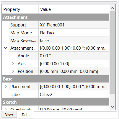
A new possibility for changing the Z distance opens up.
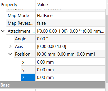
Now click on 0.00mm next to the Z direction and enter the value 100mm.
We see that our rectangle has moved by 100mm in the direction of the +Z axis. In order to move our circle so that its center coincides with the end point of the curved line by moving it by -5mm in the Y direction (we look at the dimensions of the end point of the curved line in relation to CCS).
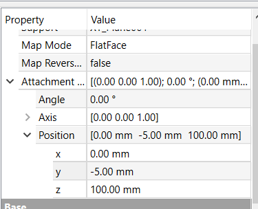
To get our 3D model, select the Additivepipe in the Combo View window by double clicking.
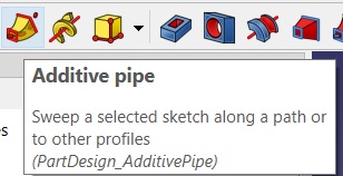
Now select the Rectangle, then activate the Additive Pipe command.
In the Combo View window, in the Section transformation, change the Transform mode to Multisection. Then click on Add Section and select Circle.
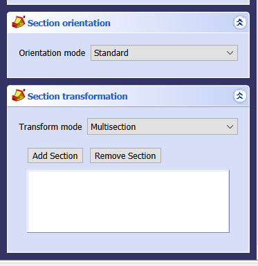
Then click OK in the Combo View window.
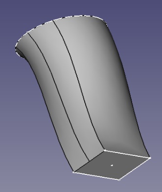
In this way, we got our 3D model that turns from a rectangle into a circle guided by a curved line.
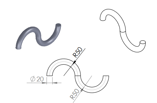
Exercise task
